The word digital in digital computer means that the information in the computer is represented by variables which takes discrete values.The digital computer is one which performs various computational tasks.The digital computers use binary number system which is 1 and 0. Computer design deals with the hardware of the computer. This aspect of computer hardware is sometimes referred to as computer implementation. Information is represented in digital computers in groups of bits.

—->> Instruction Cycle: In the computer designing , there involves computer organisation which uses registers in the instruction cycles.The instruction cycle is also called fetch-decode-execute cycle, which the central processing unit (CPU) follows from boot-up till the computer has shut down in order to process instructions.It has three important stages which are:
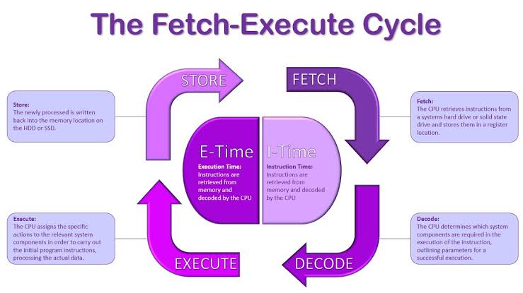
- Fetch Stage: In the fetch stage the next information to be executed is fetched from the memory address that is currently stored in the program counter.
- Decode/indirect Stage: In the decode stage the encoded instruction in the register is interpreted by the decoder
- Execute Stage: The control unit of the CPU passes the decoded information as a sequence of control signals to the relevant function units of the CPU to perform the required actions by the instruction, such as reading values from registers, performing mathematical or logic functions on Arithmetic and logic Unit, and writing the result back to a register.
- Repeat Cycle/ interrupt cycle: At the completion of the Execute Cycle, a test is made to determine whether any enabled interrupt has occurred or not. If an interrupt has occurred then Interrupt Cycle occurs.
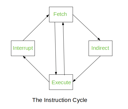
The Indirect Cycle is always followed by the Execute Cycle. The Interrupt Cycle is always followed by the Fetch Cycle. For both fetch and execute cycles, the next cycle depends on the state of the system.
—->> Memory reference instructions: The decoded output Di for i = 1,2,3,4,5 and 6 from the operation decoder that belongs to each instruction is included in the table.The effective address of the instruction is in the address register AR and was placed there during timing signal T(2) when I=0, or during timing signal T(3) when I=1. The execution of the memory reference instructions starts with the timing signal t(4).The data must be read from memory to a register where they can be operated on with logic circuits.There are seven memory reference instructions which are as follows :
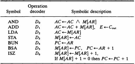
AND TO AC: This is an instruction that performs an AND logic operation on pairs of bits in AC and the memory word specified by the effective address.The result is transferred to AC. Two timing signals are needed to execute this instruction.The clock transistion associated with the timing signal t(4) transfers the operand from memory into DR. Likewise the timing signal associated with t(5) transfers the results between the contents of DR and AC.
ADD TO AC: This instruction adds the contents of the memory word specified by the effective address to the value of AC.The sum is transferred into AC and the output carry C(out) is transferred to E(extended accumulator) flip flop.After the instruction is fetched from memory and decoded only one output of the operation decoder will be active and that output determines the sequence of micro operations that the control flows during the execution of a memory reference instruction.
Load to AC-(LDA): This instruction transfers the memory word specified by the effective address to AC.It is necessary to read the memory word into DR first and then transfer the content of DR into AC.The reason for not connecting the bus to inputs of AC is the delay encountered in the adder and logic circuit.
Store AC-(STA): This instruction stores the content of AC into the memory word specified by the effective address.This instruction is executed with one micro operation since it is connected to a bus.
Branch Unconditionally-(BUN): This instruction transfers the program to the instruction specified by the effective address.The BUN instruction allows the programmer to specify an instruction out of the sequence and we say that the program branches unconditionally.
Branch and save return address-(BSA): This instruction is useful for branching to a portion of a program called a subroutine or procedure. When executed, the BSA instruction stores the address of the next instruction in sequence into a memory location specified by the effective address. The effective address plus one is then transferred to PC to serve as the address of the first instruction in the subroutine.
Increment and skip if zero-(ISZ): This instruction increments the word specified by the effective address, and if the incremented value is equal to zero , PC is incremented by 1.

Input-Output Configurations: The terminal sends and receives serial information. Each quantity of information has eight bits of an alphanumeric code. The serial information from the keyboard is shifted into the input register INPR. The serial information for the printer is stored in the output register OUTR. These two registers communicate with a communication interface serially and with the AC in parallel.
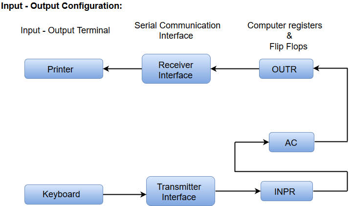
—->> Input -Output Instructions: These instructions are needed for transferring information to and AC register, for checking the flag bits and controlling the interrupt facility. These instructions have an operation code 1111 and they are recognized by the control when D(7)=1 and I = 1.
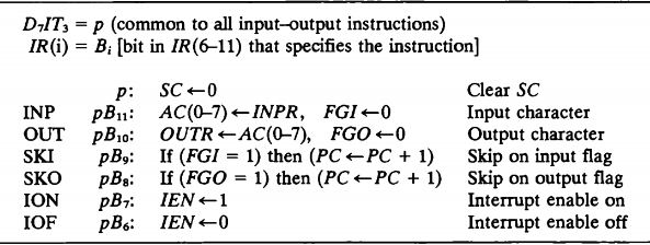
The INP instruction transfers the input information from INPR into the eight low-order bits of AC and also clears the input flag to 0. The OUT instructions transfers eight least significant bits of AC into the OUTPUT register OUTR and clears the out put flag to 0.
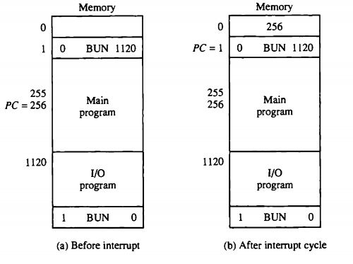
—->> Interrupt Cycle: This cycle is initiated after the last execute phase if the interrupt flip flop R is equal to 1. This flip flop is set to 1 if IEN = 1 either FGI or FGO are equal to 1. This can happen with any clock transition except when timing signals T(0),T(1) or T(2) are active.The interrupt cycle stores the return address into memory location 0, branches to memory location 1, and clears IEN, R and SC to 0.
*LINKS OF VIDEOS:
- https://www.youtube.com/watch?v=OUDtzDs6D34
- https://www.youtube.com/watch?v=igMtmHaff8M
- https://www.youtube.com/watch?v=SFsnysyVhzA
- https://www.slideshare.net/mekind/basic-computer-organization-and-design-30538899
